
|
|
|
Metal Lathe Tools: Cemented Carbide |
* Temperature at which the tool material begins to soften appreciably. For HSS, it depends on the level of cobalt in the HSS.
|
|||||||||||||||||
Angles shown are good for hobbyists; grinds for production shops should consult a specialist.
When both a relief and a clearance angle are outlined (e.g., Side Relief and Front Relief), this is done to facilitate easier resharpening. It is analogous to Secondary Bevels on woodworking chisels.
Resharpening should be done when the wear land reaches 1.5 mm (1/16 inch) high.
Angles shown are the effective angles, not the ground angles. Effective angles are increased or decreased, based on the angle by which the tool is presented against the work. Additionally, the vertical alignment of the tool (vs. the center line of the work) can also change the effective Front Relief Angle.

click on the gray block to see more
All angles are given the nomenclature designated by the American Standards Association (ASA).
|
Tool Shape - End View |
||||
|---|---|---|---|---|
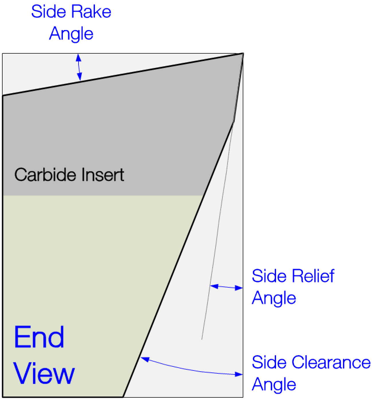
Side Clearance Angle should be 4° to 6° greater than Side Relief Angle. In selecting the Side Relief Angle, the sharpener should:
Special Notes :
|
||||
|
Material |
Side Rake Angle |
Side Relief Angle |
Side Clearance Angle |
Comments |
| Aluminium | 10° - 20° |
8° - 10° |
Side Relief
+ 4° - 6° |
|
| Aluminum Bronze | 6° - 12° | 7° - 9° | ||
| Manganese Bronze |
4° - 10° |
6° - 8° |
||
| Bronze Castings | 6° - 12° | 7° - 9° | ||
| Cast Iron - Soft (170 Brinell) |
6° - 12° |
6° - 8° |
||
| Cast Iron - Medium (250 Brinell) | 4° - 9° | 5° - 7° | ||
| Cast Iron - Hard (400 Brinell) | 0° - 5° | 3° - 5° | ||
| Cast Iron - Chilled | -10° - 0° | 2° - 4° | ||
| Copper | 10° - 20° | 7° - 9° | ||
| Monel |
4° - 9° |
6° - 8° |
||
| Magnesium | 15° - 25° | 8° - 10° | ||
| Maleable Iron |
5° - 10° |
5° - 7° |
||
|
Plastics |
10° - 25° |
9° - 11° |
||
| Steel - SAE 1020 |
8° - 15° |
6° - 8° |
||
| Steel - SAE 1040 |
6° - 12° |
6° - 8° |
||
|
Steel - SAE 1095 or 52100 |
4° - 8° |
5° - 7° |
||
| Steel - SAE 2340 |
4° - 8° |
5° - 7° |
||
| Steel - SAE 6150 |
3° - 5° |
3° - 7° |
||
| Steel - Heat Treated to 350 Brinell |
4° - 6° |
0° - 4° |
||
|
Tool Shape - Side View |
|||||
|---|---|---|---|---|---|
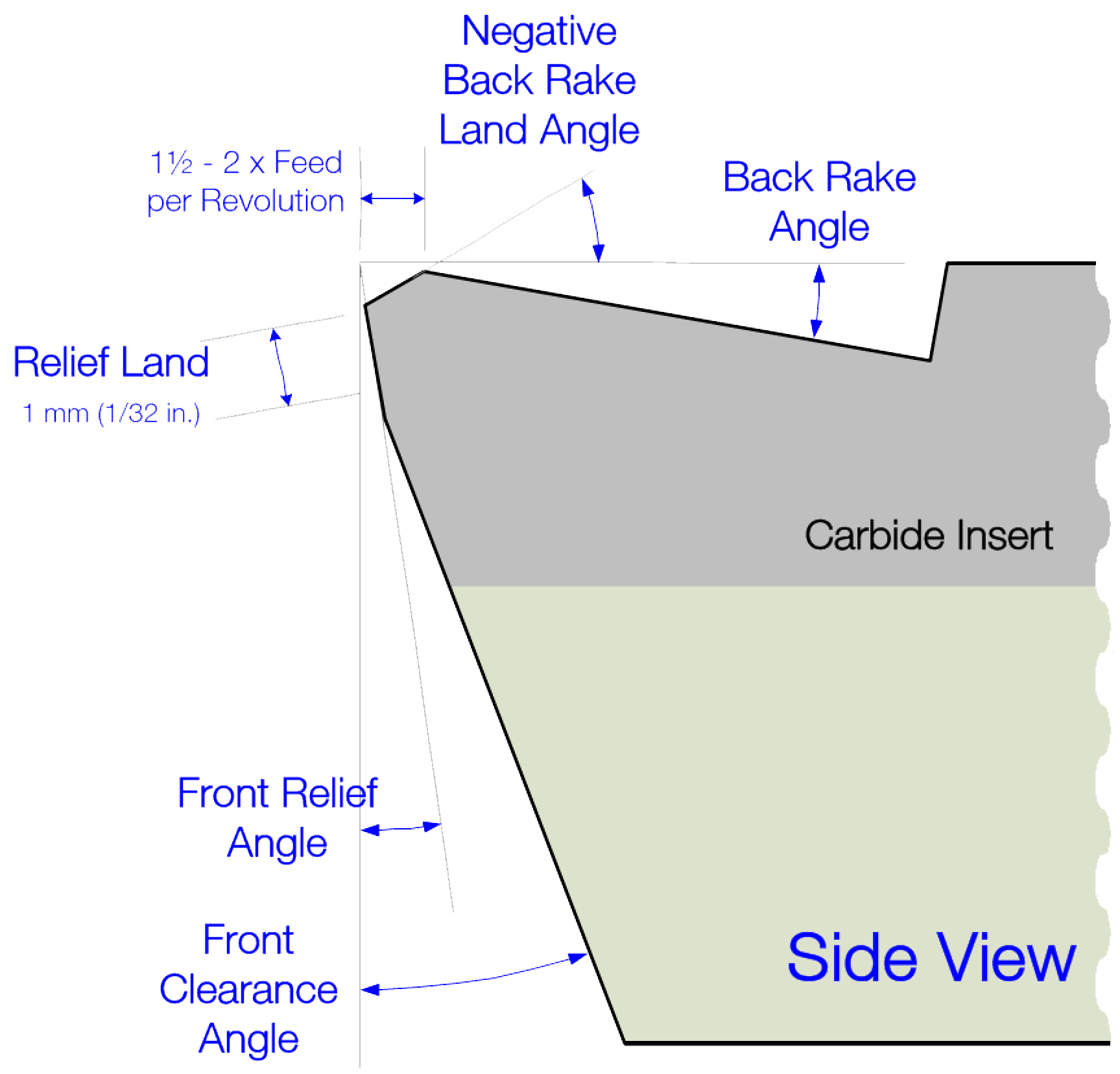
Front Clearance Angle should be 4° to 6° greater than the Front Relief Angle. The Back Rake Angle, as shown in the picture to the right, is positive.
If a combined Negative Back Rake Angle and a Back Rake Angle is used (as shown in the picture), the width of the land for the Negative Back Rake Angle is 1.5 - 2 x the feed per revolution. Another reason to introduce a Negative Back Rake Land is to reduce the ability for introducing breaks or cracks on the intersection between the Back Rake and the Front Relief. This is sometimes called "stoning off" or "dubbing" the edge.
Special Notes :
|
|||||
|
Material |
Front Relief Angle |
Front Clearance Angle |
Back Rake Angle |
Negative Back Rake Angle |
Comments |
| Aluminium | 8° - 10° |
Front Relief + 4° - 6° |
5° - 8° |
90° angle to Front Relief Angle (can be more than 90°) |
|
| Aluminum Bronze | 7° - 9° | ||||
| Manganese Bronze | 6° - 8° | ||||
| Bronze Castings | 7° - 9° | ||||
| Cast Iron - Soft (170 Brinell) | 6° - 8° | ||||
| Cast Iron - Medium (250 Brinell) | 5° - 7° | ||||
| Cast Iron - Hard (400 Brinell) | 3° - 5° | ||||
| Cast Iron - Chilled | 2° - 4° | ||||
| Copper | 7° - 9° | ||||
| Monel | 6° - 8° | ||||
| Magnesium | 8° - 10° | ||||
| Maleable Iron | 5° - 7° | ||||
| Plastics | 9° - 11° | ||||
| Steel - SAE 1020 | 6° - 8° | ||||
| Steel - SAE 1040 | 6° - 8° | ||||
| Steel - SAE 1095 or 52100 | 5° - 7° | ||||
| Steel - SAE 2340 | 5° - 7° | ||||
| Steel - SAE 6150 | 5° - 7° | ||||
| Steel - Heat Treated to 350 Brinell | 4° - 6° | ||||
|
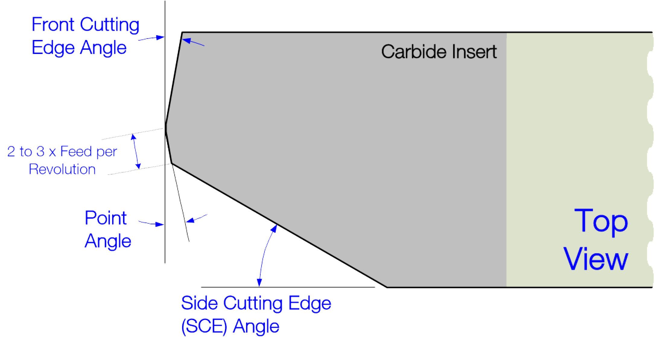
Tool Shape - Top View |
|||||
|---|---|---|---|---|---|
Top View - Point Angle 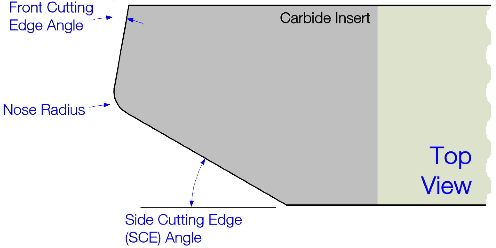
Top View - Radius
Increases in the Side Cutting Edge Angle will :
|
|||||
|
Use |
Side Cutting Edge (SCE) Angle |
Point Angle |
Front Cutting Edge Angle |
Comments |
|
|
Range |
Recom. |
||||
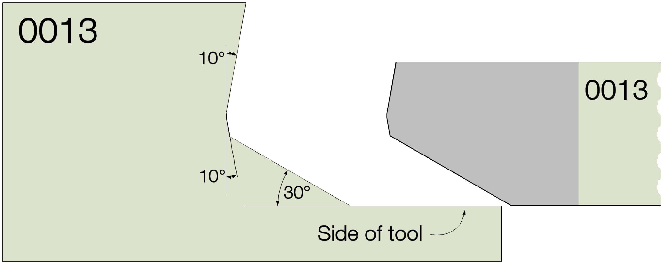
| Roughing Out | 10° - 60° | 30° | 5° - 10° | It is recommended that the Point and the Front Cutting Edge Angles match. | |
| Finishing - if a square corner is required | n/a | 0° | n/a | 5° - 10° | If a square edge is not needed, a point angle (or a nose radius) can be used. |
Contour Gauge
For resharpening, a contour gauge like shown to the left is recommended. One should be made for each tool, and it should be numbered to match the tool's number.
